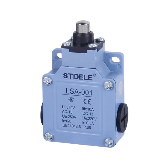
Product Overview
The LSA-001 is a vertical limit switch equipped with a sealed plunger actuator. It is used for mechanical position detection, stroke limit control, and machine operation feedback in industrial automation equipment. The plunger actuator is suitable for applications where a moving mechanical part presses the actuator directly from the correct direction.
This page describes model LSA-001 only. The product is suitable for machine tools, conveyors, industrial equipment, door mechanisms, lifting machinery, and general automation systems that require reliable mechanical position sensing.
Key Technical Data
| Item | LSA-001 |
|---|---|
| Product type | Vertical limit switch |
| Actuator type | Sealed plunger |
| Contact form | 1NO + 1NC |
| NO terminal | 13–14 |
| NC terminal | 11–12 |
| Protection degree | IP66 |
| Operating force | 800 g max. |
| Release force | 400 g min. |
| Pre-travel | 1.8 mm max. |
| Tripping position | 2.0 mm, TP ±10% |
| Overtravel | 4.0 mm min. |
| Total travel | 5.8 mm min. |
| Electrical life | 300,000 operations or above |
Product Display
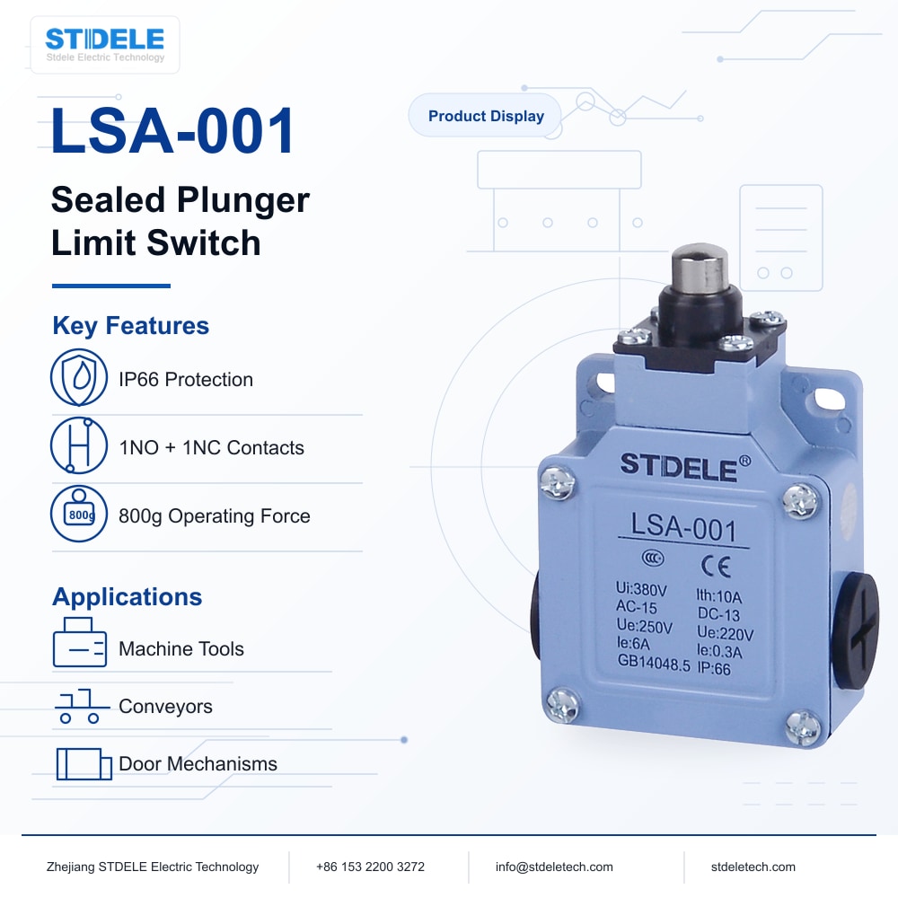
The LSA-001 uses a compact vertical switch body with a sealed plunger actuator. The product structure includes a reinforced housing, aluminum alloy base, sealed actuator section, terminal cover, and three-way outgoing line design for flexible wiring installation.
Features
- Double-circuit contact structure for NO and NC control logic.
- Sealed plunger actuator for direct mechanical position detection.
- Built-in contact box with double-spring mechanism for stable contact action.
- High mechanical strength with intensive plastic and aluminum alloy structure.
- Water-proof and oil-proof construction for industrial environments.
- IP66 protection degree when properly installed and sealed.
- Smooth operation with sufficient overtravel allowance.
- Three-way outgoing line design for easy field wiring.
- Suitable for machine tools, conveyors, door mechanisms, lifting equipment, and automation systems.
Drawing
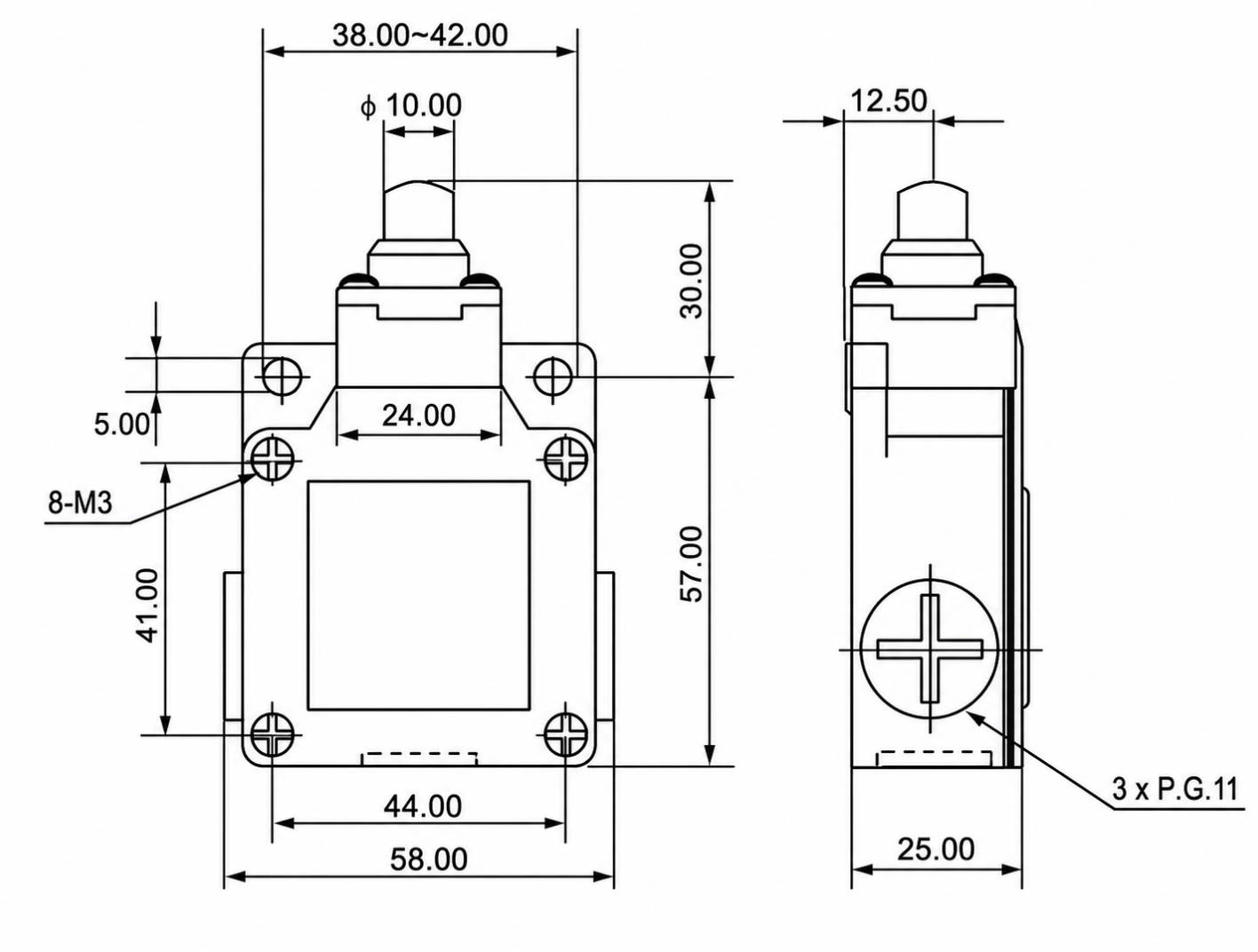
Outline and Mounting Dimensions
The drawing is used to confirm the outline structure, mounting hole position, plunger operating direction, actuator clearance, and cable entry direction of the LSA-001. Before installation, check that the moving mechanical part can press the plunger smoothly without side loading or excessive impact.
The actuator should be operated in line with the plunger movement direction. Avoid using the plunger as a mechanical stopper unless the machine structure provides proper travel limitation.
Contact Form
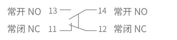
LSA-001 uses a double-circuit contact structure with one normally open contact and one normally closed contact. The normally open contact uses terminals 13–14 and closes when the actuator is operated. The normally closed contact uses terminals 11–12 and opens when the actuator is operated.
Wiring logic should be selected according to the control circuit. Safety-related circuits often use NC logic, but the final selection should follow the electrical design of the equipment.
Ratings
Rated Load Table
| Rated
Voltage |
Resistance
Load NC |
Resistance
Load NO |
Lamp
Load NC |
Lamp
Load NO |
Inductive
Load NC |
Inductive
Load NO |
Motor
Load NC |
Motor
Load NO |
|---|---|---|---|---|---|---|---|---|
| 125VAC | 5A | 5A | 1.5A | 0.7A | 3A | 3A | 2A | 1A |
| 250VAC | 5A | 5A | 1A | 0.5A | 3A | 3A | 1.5A | 0.8A |
| 8VDC | 5A | 5A | 3A | 3A | 5A | 4A | 3A | 3A |
| 14VDC | 5A | 5A | 3A | 3A | 4A | 4A | 3A | 3A |
| 30VDC | 5A | 5A | 3A | 3A | 4A | 4A | 3A | 3A |
| 125VDC | 0.4A | 0.4A | – | – | – | – | – | – |
| 250VDC | 0.2A | 0.2A | – | – | – | – | – | – |
Load Type Notes
- Inrush current: NC below 24A, NO below 12A.
- Inductive load has a power factor of 0.4 minimum for AC and a time constant of 7 ms maximum for DC.
- Lamp load inrush current is approximately 10 times the steady-state current.
- Motor load inrush current is approximately 6 times the steady-state current.
- For inductive, lamp, or motor loads, the inrush current should be considered during circuit design.
Specifications
Electrical
| Item | Specification |
|---|---|
| Contact resistance | 25 mΩ max., initial value |
| Insulation resistance | 100 MΩ min. at 500 VDC |
| Dielectric strength 1 | 1000 VAC, 50/60 Hz for 1 minute between terminals of the same polarity |
| Dielectric strength 2 | 1500 VAC, 50/60 Hz for 1 minute between current-carrying and non-current-carrying metal parts |
| Dielectric strength 3 | 1500 VAC, 50/60 Hz for 1 minute between each terminal and ground |
| Electrical life | 300,000 operations or above |
Mechanical
| Item | Specification |
|---|---|
| Operating speed | 5 mm to 0.5 m/s |
| Operating frequency | Electrical: 30 operations/min |
| Vibration | 10–55 Hz, 1.5 mm double amplitude |
| Shock durability | 1000 m/s², approx. 100G |
| Shock malfunction | 300 m/s², approx. 30G |
Environmental
| Item | Specification |
|---|---|
| Ambient temperature | -20°C to +70°C, with no icing |
| Humidity | <95% RH |
| Degree of protection | IP66 |
Operating Characteristics
The following operating characteristics apply to model LSA-001 only. The mechanical stroke and actuator position should be checked according to the installation direction and the moving part of the machine.
| Parameter | Description | LSA-001 |
|---|---|---|
| OF | Operating force, maximum | 800 g |
| RF | Release force, minimum | 400 g |
| PT | Pre-travel, maximum | 1.8 mm |
| TP | Tripping position | 2.0 mm, TP ±10% |
| MD | Movement differential, maximum | 1.2 mm |
| OT | Overtravel, minimum | 4.0 mm |
| TT | Total travel, minimum | 5.8 mm |
| Rotary indexing | Actuator head indexing angle | – |
Selection Guide
Actuator and Motion Direction
LSA-001 uses a sealed plunger actuator. It is suitable for applications where the moving part presses the plunger in a straight direction. The plunger should not receive excessive side force, and the machine structure should include a suitable stopper or travel limit.
Electrical Load and Contact Rating
Before selecting LSA-001, confirm whether the circuit is AC or DC, the operating voltage, current, load type, and whether the control system uses NO or NC logic. For motor, lamp, or inductive loads, select the switch according to the inrush current and not only the steady-state current.
Stroke, Overtravel and Reset
For LSA-001, the pre-travel is 1.8 mm maximum, the tripping position is 2.0 mm with TP ±10%, overtravel is 4.0 mm minimum, and total travel is 5.8 mm minimum. The moving part must operate the plunger reliably without over-compression. After actuation, the plunger must return smoothly to its original position.
Installation Environment
LSA-001 has an IP66 protection degree and is suitable for industrial environments with dust, oil mist, and water exposure. It is not designed for continuous immersion. Avoid direct high-pressure water jet unless additional protection is used. Cable entry and cover sealing must be properly installed.
Wiring and Contact Logic
The normally open contact uses terminals 13–14, and the normally closed contact uses terminals 11–12. Select the contact logic according to the control circuit. Safety or fault-detection circuits often use NC logic, but the final wiring method must follow the machine electrical design.